
The Aim of Robotics in Orthopedic Surgery
Osteoarthritis in loaded joints is the most common cause of musculoskeletal disability and pain worldwide1 and a major field of reconstructive surgery in orthopedics.


Osteoarthritis in loaded joints is the most common cause of musculoskeletal disability and pain worldwide1 and a major field of reconstructive surgery in orthopedics.

1. Open the femoral canal with a 9.5 mm intramedullary drill (Figure 1).
Instrument assembly:
a. Attach the selected valgus angle bushing (5°, 6° or 7°) to the valgus alignment guide. Check the bushing position to make sure that “left” is facing anteriorly (up) when operating on a left knee and “right” is facing anteriorly (up) when operating on a right knee.
b. Attach a modular T-handle to the IM rod and insert through the alignment assembly (Figure 2).
c. Assemble the distal femoral cutting block onto the valgus alignment guide. Positioning the block at the “primary” resection level will ensure the cut will equal the distal thickness of the femoral prosthesis. Lock by pressing the lever in a horizontal position toward the medial side (Figure 3).
Tip: If desired, the distal femoral cutting block may be set to resect an additional +2, +5 or +7 mm of bone.
2. Slide the intramedullary rod of the assembly into the femoral canal until the alignment guide contacts the distal femur (Figure 3).
Tip: It is acceptable for only one side of the guide to touch bone.
3. Orient the rotation of the assembly neutral to the posterior condyles (even amounts of posterior condyles being exposed) (Figure 4) and impact one or both of the floating spikes into the distal femur.

Instrument assembly:
a. Insert the ankle clamp into the distal end of the alignment tube and thread the locking pin into the ankle clamp (Figure 22).
b. After the ankle clamp is moved into the proper position, lock into place with the gold knob.
c. Choose the correct left or right tibial cutting block.
Instrument assembly:
a. Place the appropriate left or right tibial cutting block on top of the disc on the non-spiked fixation rod (Figure 23). Tighten the central knob to lock the block into position.
b. Introduce the rod into the Extramedullary Assembly andadjust and lock the cam in the assembly (Figure 23).

1. Place the arms of the extramedullary alignment clamp around the ankle, and adjust the distal M-L slide directly over the middle of the tibiotalar joint, which is also approximated by the second ray of the foot proximal to the malleoli (Figure 24). The cutting block on the proximal end of the assembly should be proximal to the tibial tubercle (Figure 25).
2. Assess rotation of the alignment guide and slope of the cutting plane. The goal is to align the extramedullary alignment assembly rotationally so that it aligns over the medial third of the tibial tubercle and over the second toe (Figure 26).
3. Rotational alignment is critical due to the 3º posterior sloped cut. The slope can be adjusted according to the patient’s anatomy (Figure 27).
Note: 3-5° of slope is built into the articular insert (depending on which insert is chosen) and 3º of slope is built into the tibial cutting block. A slope in-line with the saggital mechanical axis of the tibia should usually be chosen (Figure 27).
Tip: Neutral or minimally sloped alignment may be achieved by palpating the fibula followed by aligning the alignment guide parallel to the fibula.
These alignment rods couldn’t prevent the accuracy for the safe zone results after TKA, which lead in the 1990’s to develop computer assisted surgery (CAS), namely Computer Navigation in TKA. With this technique the surgeon is able to measure the alignment intraoperatively and can calculate the balance between the extension and flexion gap before cutting. An important detail for postoperative outcome in terms of motion and stability of the knee. The Computer Navigation in TKA is similar to GPS tracking, where at least three vectors are detected and define the position. A double infrared camera and detector is sending constantly signals, reflected by three tracking balls on the femur and tibia. With vector analysis, an image of the real position of femur and tibia can be visualized on the computer screen. A stylus with three tracking balls placed over the surfaces of femur and tibia in the joint can finally map the knee for planning.
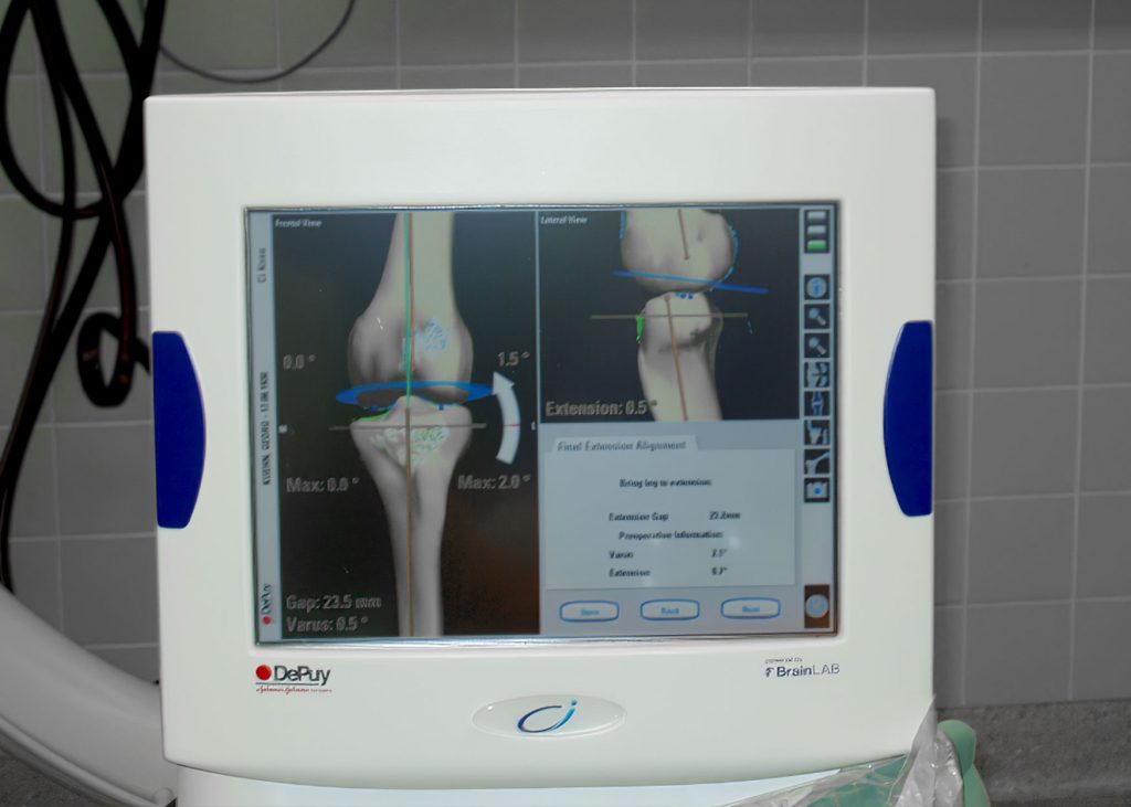
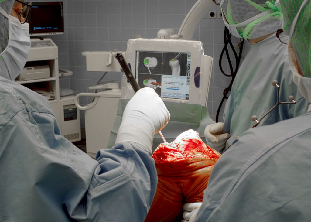
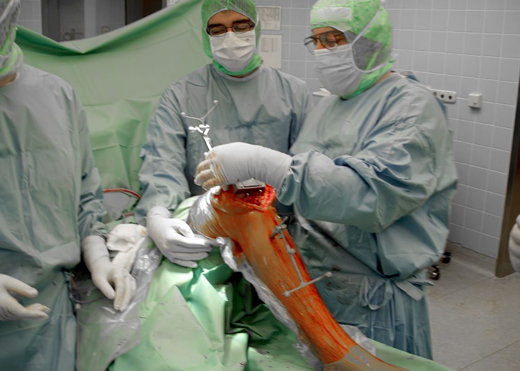
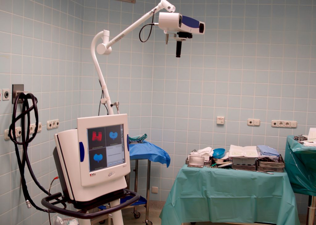
A comparison study of the postoperative alignment could show that there is a reduction in outliers (from 12 to 2) using Computer Navigation in TKA and there is a tendency of more accuracy towards the neutral alignment in the Navigation group4.
| N = -100 | Conventional | Navigation |
| Deviation of leg axis between ± 3° | 38/50 76% | 48/50 96% |
| Average of Deviation | 2,2° + 2,2° | 1,3° + 1,1° |
Originally copied from the car industry, in the 1990’s the first Robotic Hip Replacement (Robodoc) failed, because of extreme exposure of the femur bone resulting in soft tissue damage and limping.

A comparison study of the postoperative alignment could show that there is a reduction in outliers (from 12 to 2) using Computer Navigation in TKA and there is a tendency of more accuracy towards the neutral alignment in the Navigation group4.
Originally duplicated from the car industry, in the 1990’s the first Robotic Hip Replacement (Robodoc) failed, because of extreme exposure of the femur bone resulting in soft tissue damage and limping.

30 years later, learned from the early mistakes in Robodoc, with the confidence of Computer Navigation in TKA, the newest Robotics in TKA combines Navigation and the Robotic burring of the bone in one system. The first step of this technique is like the Navigation technique. The axis and surfaces of the bones are mapped and visualized on the screen. Followed by onsite planning of the prosthesis at the screen, respecting the ligament balance and gaps. The new step is that the execution of the cuttings is done by a robotic burr. The burr is controlled by an ultrafast infrared camera and four tracking balls and has the size of a pistole. The accuracy of the cutting is 0.1mm and 0.1 degree from planning, which is factor 10 times better than Navigation and factor 20 than conventional.
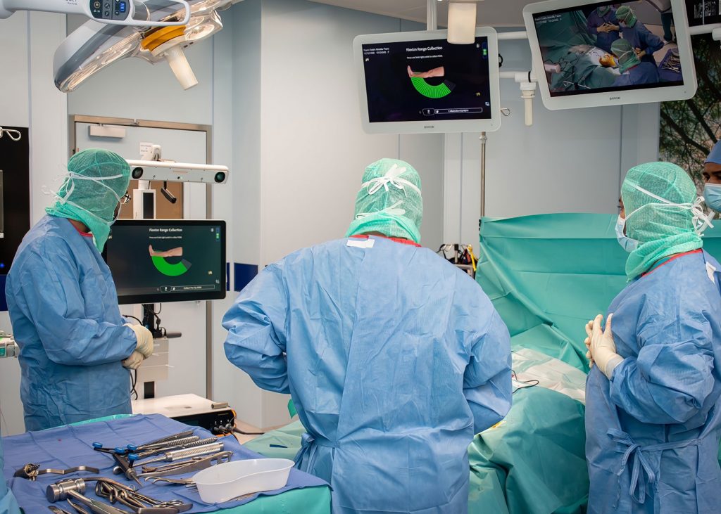
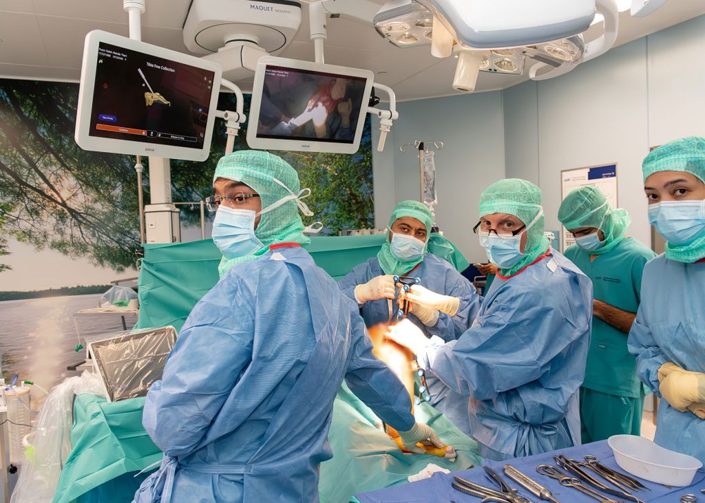
At Fakeeh University Hospital Dubai two patients for knee replacement were treated with robotic assisted surgery so far. The outcome regarding accuracy, speed of recovery, range of movement and pain management is outstanding.
Remarkable result of a 71-year-old female, 35.2 BMI, full weight bearing on day 2 post-surgery, day of discharge on 6th day, climbing stairs freely after 4 weeks. In x-ray, the resulting leg axis is neutral with 0-degree deviation from planning (left knee replacement on 11th August 2022 Fakeeh University Hospital, right knee replacement 2019 UK).
For the next FUH Medical Review
©2021 Fakeeh University Hospital. All Rights Reserved
To FUH Medical Review